
Thank you for choosing Gunstreet. Below is the instructions for a Modern Coil Cut Wiring to be installed in your 67 style Flying v
Click the photos to enlarger
Installing Pickups

Pickup Color Codes
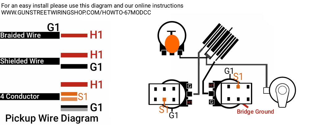
For this tutorial we will be using Bare Knuckle Color Codes. Each pickup brand uses their own set of color codes. So these colors might not match your pickups. We have included this diagram showing you all the color codes for other brands. In Order to install your pickups to the this harness you need to combine the ground and Bare Wire to make the "Ground" and then combine the two Series Wire to make the Series Link.
Bare knuckle Pickup Color Code key
red= H1/Hot Output
Green/white= S1/Series Link
Black/Bare=G1/Ground


Neck Volume: Neck Pickup Install-Part 1 "Hot Output"
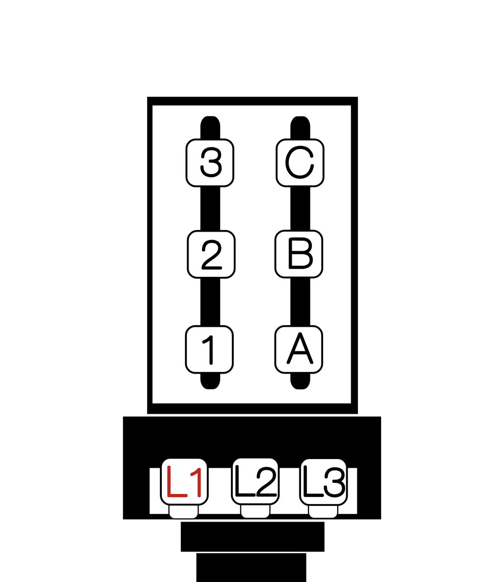
Solder the Red "Hot" Pickup wire to the First Lug on the potentiometer. Labeled L1 on diagram above If not sure which wire is hot please refer to your pickups manufacturers instructions. In Bare Knuckles case it is the red wire.

Neck Volume: Neck Pickup Install- Part 2 "Series Link"
Solder the two Series wires to the Middle Lug on the left side of potentiometer Labeled 2 on Diagram Above. If you not sure which wires are the Series please refer to your pickups manufacturers instructions. In Bare Knuckles case it is the Green and White wires.

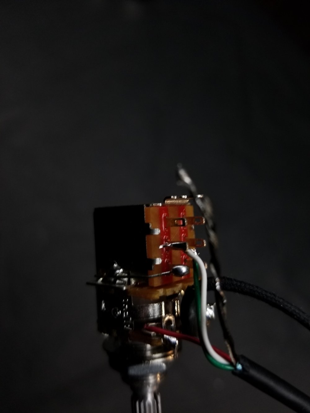
Neck Volume: Neck Pickup Install- Part 3 "The Ground"
Solder the two Ground wires to the casing of the potentiometer. See picture below. If you not sure which wires are the Ground please refer to your pickups manufacturers instructions. In Bare Knuckles case it is the Black and Bare wires.
Repeat these steps for the Bridge Volume


Grounding the Harness
Solder the Ground Wire coming from your guitar bridge to the Casing of any pot. in this case the best location was the Tone Pot